
The same weight can ask more of a robot
A robot advertised with a particular payload is not promising to move that weight in every arrangement. A compact part held close to the wrist and a long part held far away can weigh the same while placing very different demands on the arm.
Universal Robots makes this distinction explicit in its UR30 documentation: permissible payload depends on the distance between the tool flange and the payload's center of gravity. The gripper and the workpiece both matter. Its expanded payload region also comes with orientation and reach conditions, not simply a larger number on the specification sheet.1
The useful buying question is therefore not just "How many kilograms?" It is "Can this robot handle our complete load, in our working positions, through our required cycle?"
A simple way to see the difference
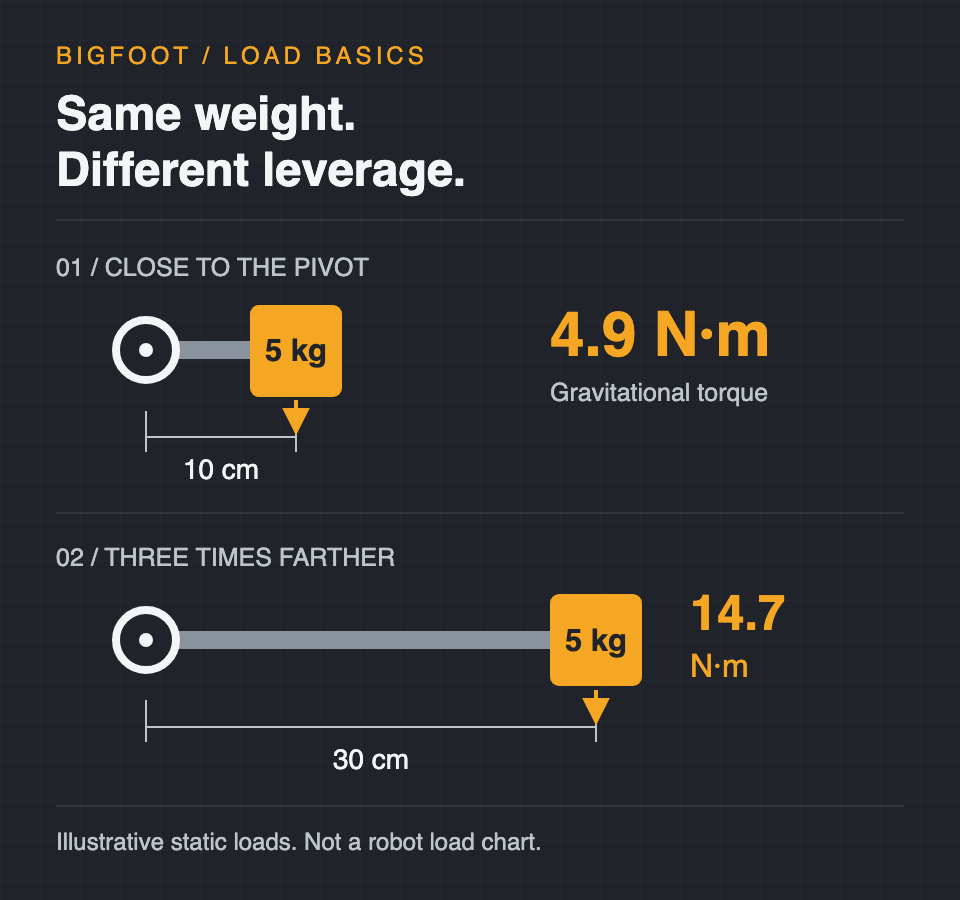
Imagine a 5 kg load whose center of gravity sits horizontally 10 cm from a pivot. Using 9.81 m/s² for gravitational acceleration, its weight creates about 4.9 newton-metres of torque about that pivot. Move the same load to 30 cm and the torque becomes about 14.7 newton-metres: three times as much, without adding any weight.
That follows the basic relationship between force and its perpendicular lever arm.4 It is an illustrative static calculation, not a robot's load rating. It leaves out the gripper's own weight, acceleration, joint geometry and the other loads in a real machine. A robot cannot be selected or declared safe from this example alone.
Count the tool, then describe the load
The workpiece is not the whole payload. Start with the complete carried assembly, including the tool and attachments, and use the manufacturer's definitions for the relevant load case.
Mass and center of gravity still do not describe everything. Rotational inertia describes how mass is distributed relative to an axis of rotation. Moving mass farther from that axis increases its contribution to inertia; a long object can consequently behave differently from a compact one with the same weight.5
For its UR7e, Universal Robots provides separate settings for mass, center of gravity and inertia, with multiple payload configurations for changing conditions such as picking up and releasing a workpiece. Those are model- and software-specific instructions, not universal coordinate conventions.2
Check the cycle, not just the static pose
An acceptable load arrangement does not automatically preserve the speed seen in a demonstration. UR30 documentation says that increased payload can reduce acceleration and speed, and that the controller adjusts acceleration when the payload properties are configured correctly. A heavier-capacity operating region may also restrict the available motion.1
ABB's RobotLoad add-in illustrates the broader evaluation needed. Its load cases can include a gripper, parts and upper-arm loads; its checks consider quantities including center of gravity, inertia and static torque. The manual also names limits to the tool's coverage, including frame-arm loads it does not verify. Passing one calculation is not proof that every load or application constraint has been checked.3
What to ask before choosing an arm
- What is the mass and center of gravity of the complete loaded assembly, not just the part?
- Which empty, loaded and changed-tool states need their own evaluation?
- Does the manufacturer's load analysis cover the required orientations, reach and motion?
- What cycle time remains after the actual load and its limits are included?
- Which loads or application conditions are outside the chosen analysis tool's scope?
The conclusion: a payload number is a starting filter, not a complete application specification. Compare the whole load and the whole cycle. Keep load suitability separate from the safety assessment of the complete installation.
References
- Universal Robots: UR30 maximum payload. Software documentation 10.8. Page publication date not stated; observed October 20, 2026.
- Universal Robots: UR7e payload configuration. Software documentation 5.26. Page publication date not stated; observed October 20, 2026.
- ABB: Application manual, RobotLoad add-in. 3HAC080181-001, Revision B; document trace dated January 22, 2025. See pages 9, 11-12 and 18-19. Observed October 20, 2026.
- OpenStax: University Physics Volume 1, section 10.6, Torque. Page update date not stated; observed October 20, 2026.
- OpenStax: University Physics Volume 1, section 10.5, Calculating Moments of Inertia. Page update date not stated; observed October 20, 2026.